
CUTTING MECHANICS
The method in which rock fails is important in bit design and selection. Formation failure occurs in two modes:
- Brittle failure.
- Plastic failure.
PDC bits drill primarily by shearing. A vertical penetrating force from applied weight on bit and horizontal force from the rotary table are transmitted into the cutters. The resultant force defines a plane of thrust for the cutter. Cuttings are then sheared off at an initial angle relative to the plane of thrust, which is dependent on rock strength.

PDC bits are designed and manufactured as:
- Matrix-body bit
- Steel-body bits
MATRIX-BODY
Matrix is a very hard and brittle composite material comprising tungsten carbide grains metallurgically bonded with a softer, tougher, metallic binder. It’s more erosion resistant than steel. They are preferred in high solid-content drilling mud.
Advantages-
1. Matrix is desirable as a bit material over steel because its hardness is resistant to abrasion and erosion.
2. It is capable of withstanding relatively high compressive loads.
3. For diamond-impregnated bits, only matrix-body construction can be used.
Disadvantages-
1. Compared with steel, it has low resistance to impact loading.
2. The lower impact toughness of matrix limits some matrix-bit features, such as blade height.
STEEL-BODY
Steel is metallurgically opposite of matrix. Steel bodied bits are generally preferred for soft and non-abrasive formations and large hole size. To reduce the bit body erosion, bits are hardfaced with a coating material that is more erosion resistant and sometimes receives an anti-balling treatment for very sticky rock formations such as shales.
Advantages-
1. Steel is ductile, tough and capable of withstanding greater impact loads.
2. It is capable of withstanding high impact loads, but is relatively soft and, without protective features, would quickly fail by abrasion and erosion.
3. Because of steel material capabilities, complex bit profiles and hydraulic designs are possible and relatively easy to construct on a multi-axis, computer-numerically-controlled milling machine.
Disadvantages-
1. Steel body is less erosion resistant than the matrix and, consequently, more susceptible to wear by abrasive fluids.
PDC DRILL BLANKS
These drill blanks consist of a layer of synthetic polycrystalline diamond bonded to a layer of cemented tungsten carbide using a high-temperature, high-pressure bonding technique. The resulting blank has the hardness and wear resistance of diamond which is complemented by the strength and impact resistance of tungsten carbide.

The PDC cutters are composed of a thin (up to 3.5 mm) layer of polycrystalline diamond bonded to a cemented tungsten carbide substrate. These PDC cutters are generally cylindrical (diameter generally from 8 mm up to 24 mm) but may become available in other forms (oval or triangle) and are generally chamfered to increase the cutter’s impact resistance.
Many improvements have been made in the quality and variety of the cutters and in new manufacturing techniques to prevent cutter wear and breakage. The improvements concern a better impact and abrasion resistant diamond material.
The interface geometry between the diamond layer and the tungsten carbide substrate are also improved. Due to the thermal limitations of the PDC (above 700°C the diamond layer disintegrates as a consequence of cobalt expanding), much work has been done to produce a Thermally Stable Polycrystalline (TSP) cutter, stable up to 1,150°C.
Cutters are attached to the bit body by BRAZING, using an alloy that must have the lowest possible melting point, good flow properties, excellent wettability and shear strength and bond well to tungsten carbide at low temperatures. Silver is the predominant alloy used in these alloys.
(BRAZING is a process, similar to soldering, in which a melted filler is used to join metals or ceramics together. Two work pieces are heated to a temperature higher than the melting point of the filler, but lower than the melting points of the workpieces. The melted filler is distributed between the close-fitting workpieces by capillary action. When the filler cools and solidifies, it joins the pieces together.)
BASIC DESIGN FEATURES
The design of a PDC bit is largely a compromise between many factors such as drillability (ROP), Stability, Hydraulics, Steerability, Durability.
The design mainly considers the three parts that interact with the rock formation:
1. Cutting Structure (bit profile and cutter layout characteristics);
2. Active Gauge (gauge cutters or trimmers)
3. Passive Gauge (gauge pads)
BIT PROFILE
There are three types of basic PDC bit profiles-
1. Flat or Shallow Cone
2. Tapered or Double Cone
3. Parabolic (Short/Medium/Long)

Bit profile has a direct influence on the following bit qualities:
· Stability (tendency to vibrate or drill laterally away from bit centerline).
· Steerability.
· Cutter density.
· Durability.
· Rate of penetration (ROP).
· Cleaning efficiency.
· Prevention of thermal damage to cutters by cooling.
A profile governs:
· Hydraulic efficiency.
· Cutter and/or diamond loading.
· Wear characteristics across the bit face.
It is also the principal influence on bit productivity and stability. The geometry established by the profile contributes to hydraulic flow efficiency across the bit face. Hydraulic flows directly influence ROP through the cuttings removal they provide. If cuttings are removed as rapidly as they are produced, ROP will be relatively higher. If a bit is capable of generating cuttings faster than they can be removed penetration is restricted by the cuttings, and achievement of optimal ROP is impeded. Hydraulic flows also cool bit cutting elements and prevent thermal damage to them. Cutter life influences bit life and the economic efficiency of a bit investment. Starting at the centerline of the bit and moving outward to the gauge, the profile is broken into five zones:
· Cone
· Nose
· Taper
· Shoulder
· Gauge

The choice of Bit profile depends upon the type of applications-
· Parabolic profiles are considerably more aggressive than flatter profiles and produce higher ROPs at the expense of accelerated rates of abrasive wear. As bit profile becomes more parabolic, cutter wear on the inner radii around the nose increases. Parabolic profiles are susceptible to cutter breakage by impact, particularly if insufficient cutter density exists in the nose area.
Long parabolic profiles are made up of a series of curves beginning at the cone-to-nose intersection and continuing to the outside diameter radius and gauge intersection.
· When harder formations are drilled, flat profiles and high cutter loading are required. Flatter profiles uniformly place high loading on individual cutters and increase penetration. If abrasive wear is predominant, however, parabolic profiles enable the higher cutter densities that limit penetration but increase resistance to abrasion.
Flat profiles have a single radius on the shoulder and are less aggressive than parabolic profiles.
· PDC bits most frequently incorporate large shoulder radii and primarily use either short or medium parabolic profiles. Cone angles are sufficient to stabilize the bit from unwanted deviation without hindering steerability. Such designs give bits the versatility to drill efficiently either by conventional rotary drilling or with downhole motors.
Flat and long parabolic profiles are less commonly used designs.
DRILLABILITY

The main parameters that control the drillability of the bit are
- PDC cutter characteristics
- Back Rake Angle
- Cutter layout
- Cutter count
- Cutter size.
The BACK RAKE ANGLE is defined as the angle the cutter face makes with respect to the rock. The back rake controls how aggressively cutters engage the rock formation.
Generally, as the back rake decreases, the cutting efficiency increases (high ROP) but the cutter becomes more vulnerable to impact breakage.
A large back rake angle will result in lower ROP but will enable to a longer PDC bit life. The side rake generally affects the cleaning of the cutters, as it helps to direct the cutting toward the periphery of the bit.
PDC cutter count and size are selected for a specific formation under specific operating conditions. The general rule is that small cutter and high cutter count is chosen for hard and abrasive rock formation, whereas large cutters and a reduced cutter count are preferred for soft to medium formation. The cutter count determines the number of blades required.
STABILITY
A stable bit increases the rate of penetration and bit life, improves hole quality and reduces the damage caused to downhole equipment. The three main vibration modes are axial, resulting in bit bouncing; torsional, resulting in stick-slip; and lateral, resulting in whirl motions.
Other techniques are anti-whirl bits, low friction gauge pad and full gauge contact design to make the bits more stable. A widely spread innovation consists in placing some impact arrestors (small round inserts) behind the PDC cutters, which provide a better stabilization to axial and lateral modes of vibration.
STEERABILITY
The steerability of a bit corresponds to the ability of the bit to initiate a deviation. Generally speaking, and all things being equal, the short-gauge design is more steerable than long-gauge design but may lead to poor borehole quality.
DURABILITY
Advancements in PDC cutter technology have increased the development and performance of PDC bits. Cutters have mainly been evaluated in terms of their resistances to impact and abrasion because the primary reasons of bit failure are abrasive damage and impact loading damage. Additionally, other characteristics such as interface strength, thermal stability and fatigue are also analyzed. Maximizing these properties improves cutter durability that subsequently enhances PDC bit performance and drilling efficiency.
HYDRAULICS
The size of nozzles (made of tungsten carbide) that are interchangeable depends on many factors, the main factors being the size of the bit and the recommended hydraulic program.
The bit hydraulic is fundamental for two main purposes.
First, the drilling mud cleans the cuttings from the bit and prevents bit balling. Secondly, the mud cools the cutters to maintain the temperature below the critical 700°c.
The conventional nozzles are circular and create symmetric pressure distribution at the rock interface. Some improvements have been the development of nozzles with non-circular jets (fluted jets) with specialized interior shapes. This enables a more efficient cleaning and cutter removal (increased turbulence under the bit) resulting in a higher ROP.
PDC BIT SELECTION
Today, a PDC bit is designed for a specific application, depending mainly on the rock formation to be drilled. It is, therefore, important to study the type of rock encountered during drilling, using data and logs from offset wells. The mechanical and physical characteristics of the formation (compressive strength, abrasiveness, elasticity, stickiness, pore pressure) govern the choice of PDC bit.
IADC CLASSIFICATION FOR PDC BITS
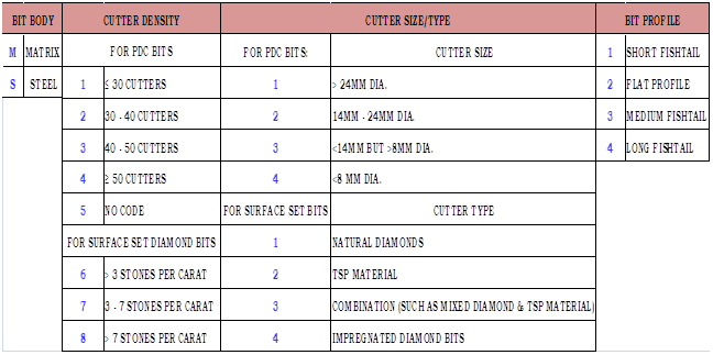
PDC bits are also denoted as for eg. 516 where, 1st digit denotes no. of blades, 2nd & 3rd digit denotes cutter size.
PDC bits come with 19mm, 16mm, 13mm & 8mm cutter size. Bigger the size of cutters more will be the rotary torque and consequently, more will be the Stick and Slip.
Note: In general, TCR bits usually have Left walk & PDC bits have Right Walk tendency in rotary drilling. But, it's not the always same depending upon the field, well profile, etc.
Nice Article
ReplyDeleteGreat information. Lucky me I ran across your blog by accident (stumbleupon).
ReplyDeleteI've book marked it for later!
Touche. Outstanding arguments. Keep up the great work.
ReplyDelete