Surveying is an inseparable part of directional drilling.
Among above mathematical models,
Tangential method is the least accurate, it assumes a straight line well path taking into consideration the inclination and azimuth at upper survey station and lower station is not accounted.
Balanced Tangential Method takes into account the upper and lower survey station and approximates well path by two equal straight line segments. The upper line segment is defined by inclination and azimuth at upper survey station and the respective values at lower survey station.
Average Angle Method assumes one straight line defined by averaging inclination and azimuth at both survey stations, intersects both upper and lower survey stations.
Radius of Curvature Method assumes that well path is not a straight line but a circular arc tangential to inclination and azimuth at each survey station.
Minimum Curvature Method is the most accurate, it further adds a Ratio Factor to smoothen the spherical arc formed by using radius of curvature method. This is practically used and accepted calculation method among all and deserve to be discussed in detail.

Note:
Surveys are recorded at regular intervals while drilling.
Reasons for Taking Surveys
- To allow accurate determination of well coordinates at a series of measured depths and determine the current location.
- To plot the well path over the measured depth.
- To measure the inclination and azimuth at the bottom of the hole and hence determine where the well is heading.
- To determine the orientation of tool face of deflection tools or steerable systems.
- To locate dog legs and allow calculation of dogleg severity values.
Accurate Knowledge of the Course of a Borehole is Necessary:
- To hit geological target.
- To avoid collision with other near by wells.
- To define the target of a relief well in the event of a blowout.
- To provide a better definition of geological and reservoir data to allow for optimization of production.
- To fulfill the requirements of local legislation if any.
For a directional driller, to successfully drill a well to the specified targets, all that's required is inclination and azimuth.
Now a days, there are many types of advanced tools used and those along with the directional survey, provides the required geophysical characteristics of the well.
There are
- MWD (Measurement While Drilling) tools and
- LWD (Logging While Drilling) tools.
- As the name suggests, MWD tools mainly measures the values of inclination and azimuth while drilling whereas, LWD tools in addition to it measures geophysical characteristics of the formations encountered while drilling.
- LWD tools are more advance and sophisticated. Use of these tools eliminate the need of separate wireline logging; thereby saving rig time.
- Although hiring of LWD tools and engineers are costly as compared to MWD's.
Survey Calculations
Directional survey in terms of 'Inclination' & 'Azimuth' of a wellbore at certain 'Measured Depth' is taken. This information is then used to calculate the actual position of the wellbore relative to the surface location. When assuming an idealized well path between the two survey stations, many mathematical models can be used such as;
- Tangential method
- Balanced Tangential method
- Average Angle method
- Radius of Curvature method
- Minimum Curvature method
Among above mathematical models,
Tangential method is the least accurate, it assumes a straight line well path taking into consideration the inclination and azimuth at upper survey station and lower station is not accounted.
Balanced Tangential Method takes into account the upper and lower survey station and approximates well path by two equal straight line segments. The upper line segment is defined by inclination and azimuth at upper survey station and the respective values at lower survey station.
Average Angle Method assumes one straight line defined by averaging inclination and azimuth at both survey stations, intersects both upper and lower survey stations.
Radius of Curvature Method assumes that well path is not a straight line but a circular arc tangential to inclination and azimuth at each survey station.
Minimum Curvature Method is the most accurate, it further adds a Ratio Factor to smoothen the spherical arc formed by using radius of curvature method. This is practically used and accepted calculation method among all and deserve to be discussed in detail.
Survey station is the measured depth at which survey is taken.
Course length (CL) is the difference between two survey stations.
Minimum Curvature Method
The inclination and azimuth at each survey station define two vectors namely inclination vector (lying in the vertical plane) and azimuthal vector (lying in the horizontal plane); and both are tangential to the wellbore trajectory. The only other piece of information available from a survey is the course length (the difference in survey measured depths) between the two stations. Minimum Curvature Method most accurately creates idealized well path between the upper and lower stations. The accuracy of the final coordinates generated by it approximates the actual trajectory of the borehole.
Let's explain the formula's used with an example.
Consider inclination and azimuth at these two survey stations.

Let's explain the formula's used with an example.
Consider inclination and azimuth at these two survey stations.
Azimuth of target is 316°.
Determine next set of values?
Determine next set of values?
Sol'n:
Upper Survey Station (MD1) is at 1914.75m
I1 = 13.6°; A1 = 315.2°; TVD1 = 1827.53m; N/S1 = 311.70m;
E/W1 = -299.27m; VS1 = 432.11m; CD1 = 432.11m; CA1 = 316.17°
Lower Survey Station (MD2) is at 1940.30m
I1 = 10.7°; A1 = 314°
Course Length (CL) = Δ MD = MD2 – MD1
Upper Survey Station (MD1) is at 1914.75m
I1 = 13.6°; A1 = 315.2°; TVD1 = 1827.53m; N/S1 = 311.70m;
E/W1 = -299.27m; VS1 = 432.11m; CD1 = 432.11m; CA1 = 316.17°
Lower Survey Station (MD2) is at 1940.30m
I1 = 10.7°; A1 = 314°
Course Length (CL) = Δ MD = MD2 – MD1
= 1940.30 – 1914.75 = 25.55m
Dog Leg = cos–1 [{sinI1 ×
sinI2 × cos(A2 – A1)} + {cosI1
× cosI2}]
= cos–1[{sin(13.6) × sin(10.7) × cos(314 – 315.2)} + {cos(13.6) × cos(10.7)}]
= 2.91
DLS = (DL × 30)/CL, when calculated per 30m.
DLS = (DL × 100)/CL, when calculated per 100ft.
DLS = (DL × 30)/CL, when calculated per 30m.
DLS = (DL × 100)/CL, when calculated per 100ft.
DLS = (2.91 × 30)/25.55 = 3.42
Ratio Factor (R.F) is simply a smoothing factor used in the following calculations. It has no other significance.
RF = Tan(DL/2) × (180/π) × (2/DL)
= Tan(2.91/2) × 180/π × (2/2.91)
= 1
“0” Dogleg Exception
When the inclination and the direction do not change between two survey stations, the dogleg and dogleg severity are equal to 0. When the dogleg is equal to 0, the formula for ratio factor (R.F.) is undefined. In this case, simply assign the ratio factor the value of 1.0.
“0” Dogleg Exception
When the inclination and the direction do not change between two survey stations, the dogleg and dogleg severity are equal to 0. When the dogleg is equal to 0, the formula for ratio factor (R.F.) is undefined. In this case, simply assign the ratio factor the value of 1.0.
Change in N/S coordinate
= 315.48
Change in E/W coordinate
= [(315.48)2 + (–303.06)2]1/2
= 437.46
Closure Azimuth
CA = Tan–1[(E/W) Total / (N/S) Total]
= Tan–1[–303.06 / 315.48]
= –43.84°
= 360°– 43.84°
= 316.16°
Note:
If the given target azimuth lies in b/w
0° to 90°, then CA = Tan–1[(E/W) Total / (N/S) Total]
90° to 180°, then CA = 180° – Tan–1[(E/W) Total / (N/S) Total]
180° to 270°, then CA = 180° + Tan–1[(E/W) Total / (N/S) Total]
270° to 360°, then CA = 360° – Tan–1[(E/W) Total / (N/S) Total]
Directional Difference (DD) is the angle between target azimuth and closure azimuth.
DD = Azimuthtarget – CA
= 316° – 316.6°
VS = CD × cos(DD)
= 437.46 × cos(–0.16°)
= 437.46
Hence,
Δ N/S = [(sinI1 × cosA1)
+ (sinI2 × cosA2)] [R.F. × (ΔMD/2)]
= [(sin(13.6) × cos(315.2)) + (sin(10.7) × cos(314))] [1 × (25.55/2)]
= 3.78
Total N/S (or) (N/S)2 = (N/S)1 + ΔN/S
= 311.7 + 3.78= 3.78
Total N/S (or) (N/S)2 = (N/S)1 + ΔN/S
= 315.48
Change in E/W coordinate
Δ E/W = [(sinI1 × sinA1)
+ (sinI2 × sinA2)] [R.F. × (ΔMD/2)]
= [(sin(13.6) × sin(315.2)) + (sin(10.7) × sin(315))] [1 × (25.55/2)]
= –3.79
= [(sin(13.6) × sin(315.2)) + (sin(10.7) × sin(315))] [1 × (25.55/2)]
= –3.79
Total E/W (or) (E/W)2 = (E/W)1 + ΔE/W
= –299.27 + –8.04
= –303.06
Change in TVD
= –303.06
Change in TVD
Δ TVD = [cosI1
+ cosI2] [R.F. × (Δ MD/2)]
= [cos(13.6) + cos(10.7)] [1 × (25.55/2)]
= 24.97
= [cos(13.6) + cos(10.7)] [1 × (25.55/2)]
= 24.97
Total TVD (or) TVD2 = TVD1 + ΔTVD
= 1827.53 + 24.97
= 1852.50
= 1827.53 + 24.97
= 1852.50
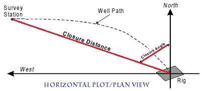
Closure Distance
CD = [(N/S)2Total + (E/W)2Total]1/2
= 437.46
Closure Azimuth
CA = Tan–1[(E/W) Total / (N/S) Total]
= Tan–1[–303.06 / 315.48]
= –43.84°
= 360°– 43.84°
= 316.16°
Note:
If the given target azimuth lies in b/w
0° to 90°, then CA = Tan–1[(E/W) Total / (N/S) Total]
90° to 180°, then CA = 180° – Tan–1[(E/W) Total / (N/S) Total]
180° to 270°, then CA = 180° + Tan–1[(E/W) Total / (N/S) Total]
270° to 360°, then CA = 360° – Tan–1[(E/W) Total / (N/S) Total]
Directional Difference (DD) is the angle between target azimuth and closure azimuth.
DD = Azimuthtarget – CA
= 316° – 316.6°
= –0.16°
VS = CD × cos(DD)
= 437.46 × cos(–0.16°)
= 437.46
Hence,
Note:
The calculation for dogleg and dogleg severity, closure and vertical section do not change when different survey methods are used.
To summarize:
*Course Length (CL) = Δ MD = MD2 – MD1
*Dog Leg = cos–1 [{sinI1 × sinI2 × cos(A2 – A1)} + {cosI1 × cosI2}]
DLS = (DL × 30)/CL, when calculated per 30m.
DLS = (DL × 100)/CL, when calculated per 100ft.
*RF = Tan(DL/2) × (180/π) × (2/DL)
*Δ N/S = [(sinI1 × cosA1) + (sinI2 × cosA2)] [R.F. × (ΔMD/2)]
Total N/S (or) (N/S)2 = (N/S)1 + ΔN/S
*Δ E/W = [(sinI1 × sinA1) + (sinI2 × sinA2)] [R.F. × (ΔMD/2)]
Total E/W (or) (E/W)2 = (E/W)1 + ΔE/W
*Δ TVD = [cosI1 + cosI2] [R.F. × (Δ MD/2)]
Total TVD (or) TVD2 = TVD1 + ΔTVD
*CD = [(N/S)2Total + (E/W)2Total]1/2
*CA = Tan–1[(E/W) Total / (N/S) Total]
If the given target azimuth lies in b/w
0° to 90°, then CA = Tan–1[(E/W) Total / (N/S) Total]
90° to 180°, then CA = 180° – Tan–1[(E/W) Total / (N/S) Total]
180° to 270°, then CA = 180° + Tan–1[(E/W) Total / (N/S) Total]
270° to 360°, then CA = 360° – Tan–1[(E/W) Total / (N/S) Total]
If the given target azimuth lies in b/w
0° to 90°, then CA = Tan–1[(E/W) Total / (N/S) Total]
90° to 180°, then CA = 180° – Tan–1[(E/W) Total / (N/S) Total]
180° to 270°, then CA = 180° + Tan–1[(E/W) Total / (N/S) Total]
270° to 360°, then CA = 360° – Tan–1[(E/W) Total / (N/S) Total]
*DD = Azimuthtarget – CA
VS = CD × cos(DD)